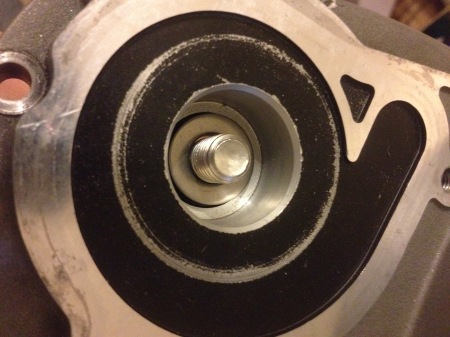
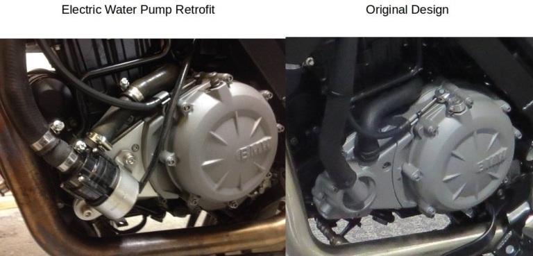
The coolant pump on the BMW G650GS motorcycle is known to fail early because one side of the impeller shaft is resting on a coolant and oil seal with no bearing. Seals are not meant to bear any load, and eventually a seal or two will fail resulting in oil and/or coolant leak. I have replaced mine a few times already and decided it was time to redesign and do better.
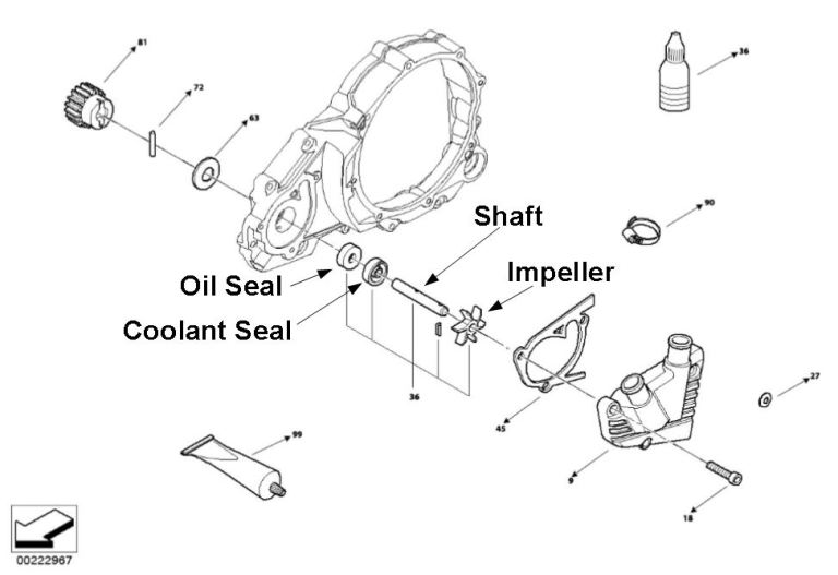
While adding a bearing would be ideal, this would involve redesigning the entire housing that holds the impeller assembly because there is not enough space behind the oil seal for a standard sized bearing.
An alternative is to graft an external electric coolant pump. The BMW G650GS was designed to run several electrical accessories at once, such as a GPS, electric heating gear, etc, so the electrical system is more than capable of supporting a pump. With an external electric pump, there will no longer be a shaft to drive the impeller or seals that will fail, avoiding coolant and oil contamination.
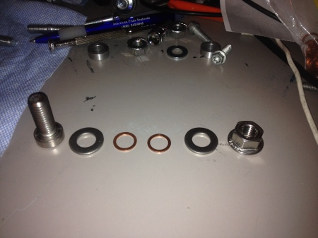
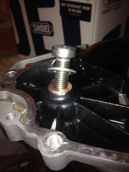
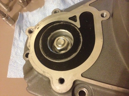
Once the impeller shaft is removed, a hole is exposed, which will allow motor oil to escape. This hole was sealed with a properly sized nut and bolt with washers and crush washers for sealing. The correct Loctite compound was also used liberally on the bolt and nut. The G650GS is a single cylinder engine, which is inherent to more vibrations than multi-cylinder engines, causing nuts and bolts to become loose over time.
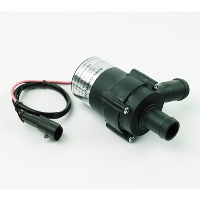
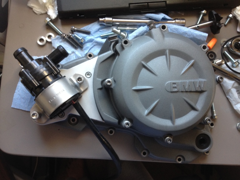
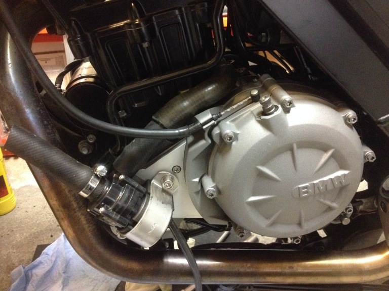
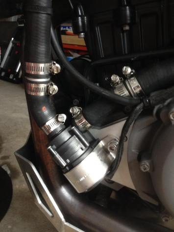
With the engine sealed, the next step was to design a mount that the electric pump can bolt onto. This particular electric pump uses magnets to spin an impeller. There are no seals in the design to fail. Referring to the image below, the electric pump is basically a cylinder with no mount points.
I used a 1 7/8″ diameter clamp with shock absorbing mount to secure the pump in place.
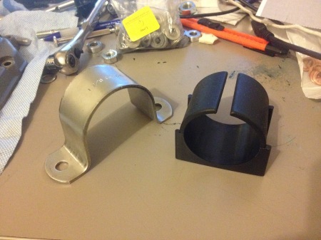
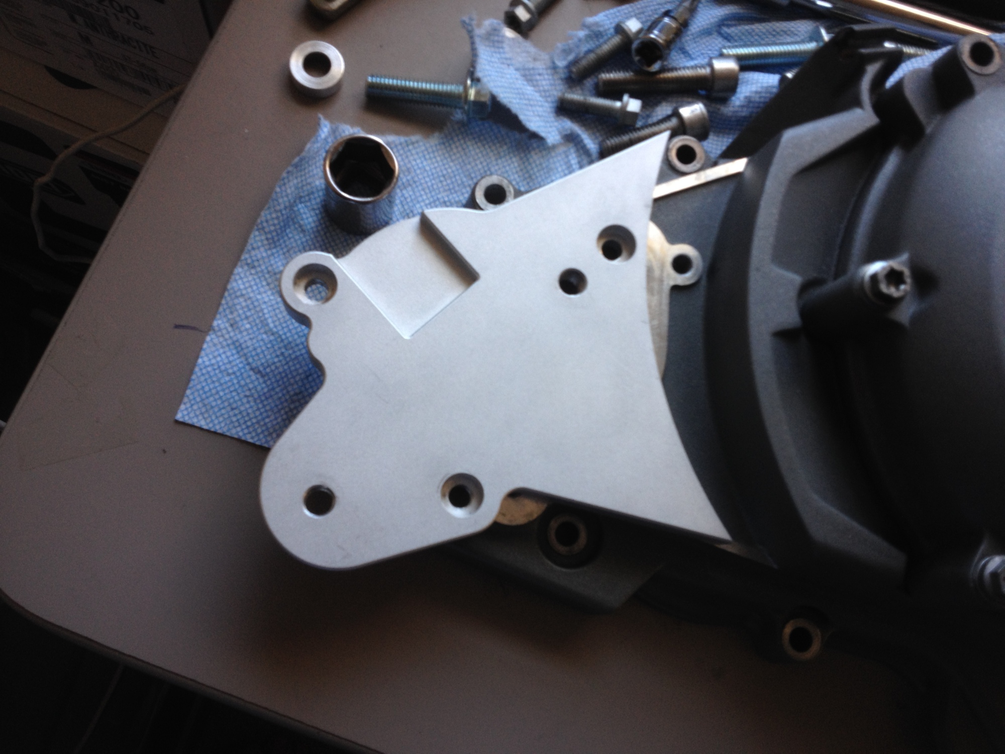
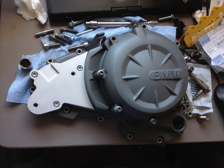
Next: precisely measure all the mounting points on the engine and the clamp to neatly package the components together. The original water pump cover had three mounting holes. The clamp requires two. Using FreeCAD and my caliper, I quickly came up with a design that will fit in place.
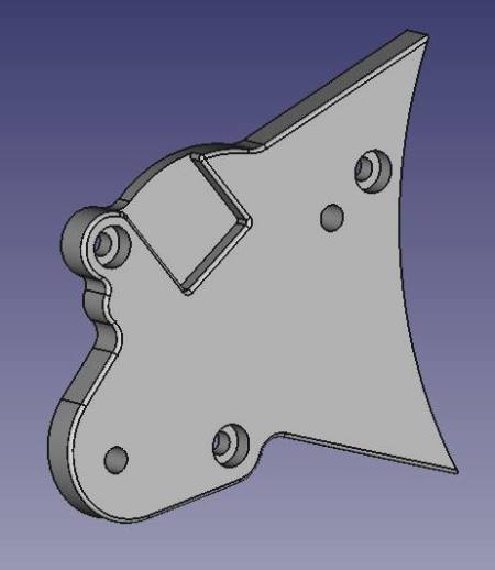
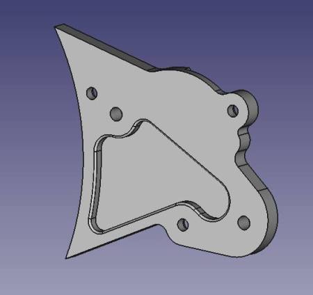
The CAD file was sent off to the CNC machinist. The result was quite beautiful, fitting perfectly.
Next: align the hoses and determine the length of the new hoses and where to cut.
The electric pump uses smaller diameter hose than the engine and radiator. While I could easily purchase brass adapters, I was not comfortable using brass with an aluminum engine because of corrosion due to two different metals. For a perfect fit, I decided to design my own aluminum adapter. I will need two: one from the radiator to the pump and the other from the pump to the engine.
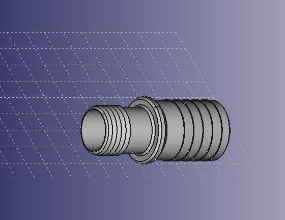
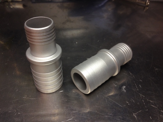
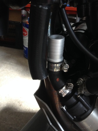
The adapters are barbed with a sharp edge to dig into the hoses and keep the hoses from coming off. The only way to remove the hose from the barbed adapter is to cut the hose. The hose clamps provides extra insurance. To drain the coolant in the future, I will just unplug the hose at the pump.
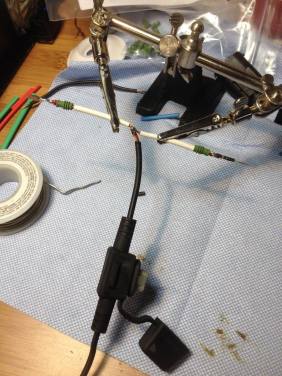
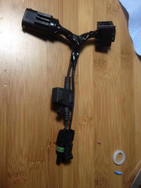
The pump requires power from the vehicle. I did not want to cut the original wire harness, so factory OEM connectors were sourced to build my own “plug and play” harness.
With power to the pump, oil in the engine, and coolant in the radiator, I was able to conduct my first test: running the engine with no air flow through the radiator. While I made sure the pump provided sufficient coolant flow beforehand, it is still vital to conduct a static test to see if the pump performs as expected and to check for leaks. This will be a “worst case” test because of the lack of air flow through the radiator.
The engine is brought up to temperature with the thermostat. Afterwards as the engine temperature starts to increase, the radiator fan will turn on. If the fan does not provide enough air flow, then the dashboard will turn on the overheating light. At this point, I should shut the engine down and reevaluate my calculations and design.
Fortunately, the design worked as expected. At 73° F, it took nine minutes before the fan turned on for about a minute. It would take another minute before the fan kicked on again with this cycle repeating itself. At no point did the overheating light turned on. I considered this test as a success. Time to do some short rides, check for leaks and functions, and do some more longer riding!
Update: I was riding in 95° F in the city, stuck in afternoon traffic. I could hear the fan turn on and off, but at no time did the overheating light turn on. There were no leaks either, so I am confident the design works.

Hello
Can you Tell me where i can get the CAD of the product?
LikeLike
Perhaps this detailed post i made on the BMW F650.com site can provide the information you’re looking for?
http://f650.com/forum/showthread.php?33054-2012-G650GS-Electric-Water-Pump-Retrofit/page2&highlight=electric+pump
If you’re interested in the pump bracket mount itself, the machine shop may be able to CNC it again for you. No promise as it has been a few years.
LikeLike
Hallo!
Our favorite bike together is the BMW 650 with a single-cylinder engine. Good to know that there are people like you who take care of the design flaw. The water pump is obviously one of the problems that were not optimally solved and that prevent a long service life. I find the solution here with the electronic water pump very elegant.
How long has this been in use? Is there any knowledge about the stability of the pump? What is the exact name of the pump and what is the delivery rate in liters per minute?
LikeLike
It’s been in use for about 4 years and no issues so far. It’s a Davies Craig Electric Booster Pump, model EBP23. Flow rate is 23 liters/min.
LikeLike