Lots of motorcycle racers bolt on expensive sensors that tell them what their lean angles are through a turn. It is a cool bragging tool and is also a measure of how confident a rider is in his or her skills and equipment.
Engineers are more curious about the lean angle for another reason: it is an important input to the traction control model. As a motorcycle rolls through a turn, its tire contact patch with the ground changes due to the tire’s profile. Keeping all other variables constant, the greater the tire contact patch, the more traction you have and vice versa. With an advanced model of a moving motorcycle and a variety of sensor inputs, such as the lean angle, a traction control model can be implemented to limit the amount of throttle the rider can use throughout the roll angles. This can prevent putting too much power to the rear wheel, resulting in a loss of traction and crashing.
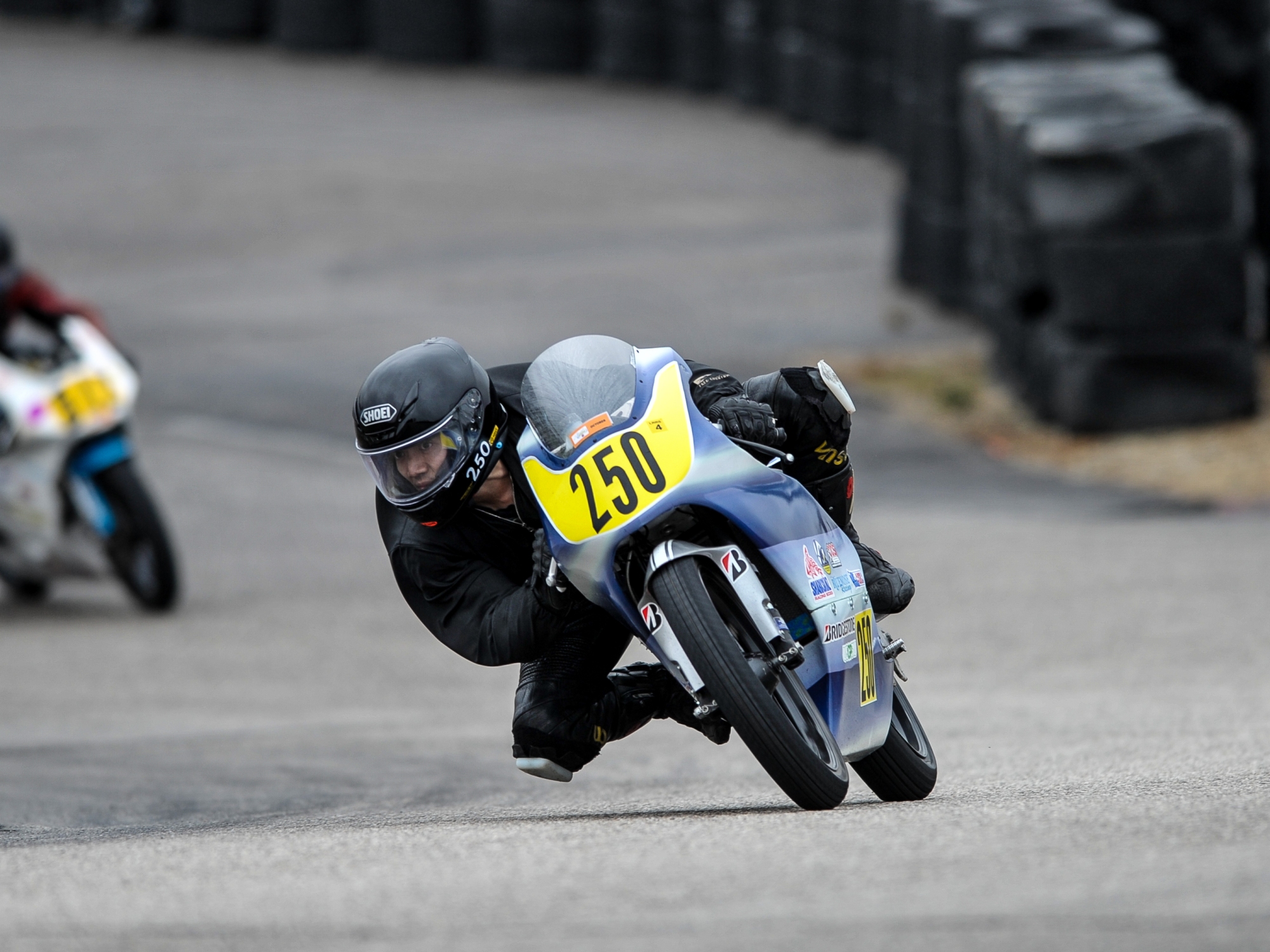
For this particular project, I was curious about methods to identify the lean angle of a motorcycle without using an expensive sensor. A few years ago, I rigidly mounted a camera on top of my gas tank for a practice session to see if it was possible to use information just from the video to calculate the lean angle. With the lean angle, I can rotate the image and simulate a gyroscopically stabilized camera without an actual mechanical gimbal.
The first step was to dissect the video in .mp4 format to individual .jpeg images, which was accomplished with FFMPEG.
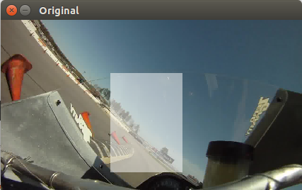
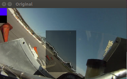
I decided to use the blue sky and horizon as a reference line to calculate the lean angle. It was not necessary to use a high resolution image (1280×720 pixel), so the images were reduced to 426×240 using OpenCV, an open source computer vision library. Even with the smaller image, only a fraction of image was necessary to identify the horizon and lean angle. For example, pixels that contain the motorcycle were not required for processing. A small search box was created for processing.
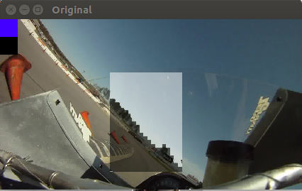
With OpenCV, I created a color threshold GUI to identify the upper and lower bounds of blue pixels to be considered as the sky and horizon.
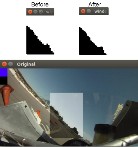
The search window was further dilated and eroded. A combination of dilation, where bright regions were further grown, and erosion, where dark regions were also grown, was used to smooth out the horizon line.
Since I have a small search window that was black (ground) and white (sky), I can use the Canny edge detector to find the horizon line.
OpenCV provides a Hough line algorithm function, which takes in a binary image and finds the line using the Hough transform. If a line segment was identified to be in excess of 50° of the previous frame’s lean angle, then I rejected those line segments and display them in red. Lines less than 50° difference were averaged together to calculate the current frame’s lean angle and displayed in green. Due to various objects that pop up above the horizon line, such as trees, the 50° was adequate as a discriminator.
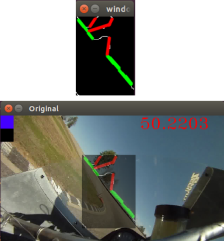
In the above video, the same process was used to trim out the trees, hence why there are other line colors as well. Because most of the trees that pop up in the horizon were of the same green, I used the same process to search for that green and removed it.
A moving average of 10 frame’s lean angles were used to reduce the noise in the video.
Unfortunately, I do not have an expensive sensor to objectively compare my results with, but by rotating the images, creating a virtual gimbal camera, I can see how well it is performing.
